# Using the ADCLearn how to configure and program the ADC on an STM32 board with Cube IDE to convert analog signals into digital values and use them in your projects.
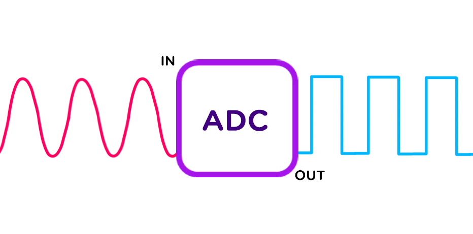
In this tutorial, we’ll learn how to use the ADC with STM32 Cube IDE.
## Requirements
* The [STM32 Cube IDE](https://www.st.com/en/development-tools/stm32cubeide.html) software
* [An STM32 development board](https://www.st.com/en/evaluation-tools/stm32-nucleo-boards.html)
* [Two prototyping cables](/chroma/images/_cables.png)
## ADC? Like the band AC/DC?
The Analog-to-Digital Converter (ADC) is a system that, as the name suggests, converts an analog signal into a digital signal. The reverse process is done by a Digital-to-Analog Converter (DAC). This allows us to transform voltages into a format that the microcontroller can process and analyze. For example, this is how you can read the values from a potentiometer, a microphone, or a light sensor. If you want to explore this technology further, check out this [webpage](https://dewesoft.com/blog/what-is-adc-converter) that explains ADCs in more depth (and no, I'm not sponsored!).
## How it works
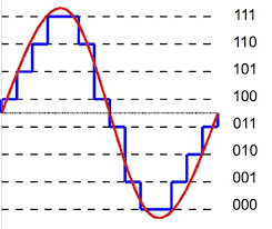 Red signal: Analog, Blue signal: Digital
1. **Sampling:** The analog signal is sampled at regular time intervals (sampling frequency).
2. **Quantization:** Each sampled value is approximated to the nearest discrete value in the binary range.
3. **Encoding:** The quantized values are encoded into a sequence of bits. The resolution of the ADC, expressed in bits, determines how many quantization levels are possible. If we denote \(n\) as the number of bits, the number of levels is:
$$
\text{resolution} = 2^n
$$
For example, on the STM32 board used in this tutorial ([NUCLEO H7A3ZI-Q](https://www.st.com/en/evaluation-tools/nucleo-h7a3zi-q.html)), the ADC is 12-bit: it can represent \(2^{12} = 4096\) levels (from 0 to 4095).
## Configuration
Generally, on STM32 boards, pins A0 to A5 have ADC capability (but it's always a good habit to check the datasheet!). We'll do a simple test to check the minimum and maximum ADC levels.
To do this, connect one analog pin to +5V (here A0) and another to GND (here A1):
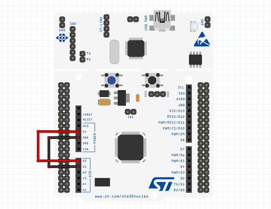 Wiring
Now, in CubeIDE:
* Create a new project and open CubeMX (.ioc window).
* Identify which pins correspond to A0 and A1. You can find mappings between "Ax" and "PAx" by checking the [pinout configuration](https://os.mbed.com/platforms/ST-Nucleo-H7A3ZI-Q/#board-pinout) of your board. In my case, A0 ↔ PA3 and A1 ↔ PC0.
* Then configure each pin as ADC input (e.g., "ADCx_INPx"). My setup:
* PA3: ADC1_INP15
* PC0: ADC2_INP10
Now configure the pins with an ADC (like "ADCx_INPx"). Here's the config I used:
* PA3: ADC1_INP15
* PC0: ADC2_INP10
{{< callout context="caution" title="Tip" icon="outline/bulb" >}}
Note that a pin may support multiple ADCs. I could’ve swapped ADC1 and ADC2 or even used ADC3. However, make sure **not to configure the same ADC on both pins simultaneously**!
{{< /callout >}}
In the "ADC" tab on the left, select ADC1 and configure as follows:
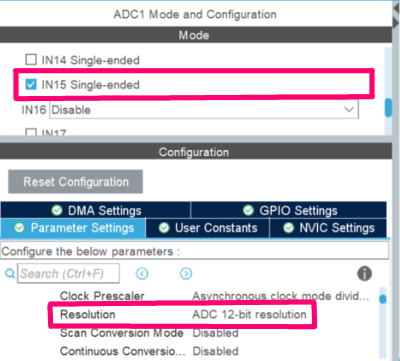
* Check IN15 Single-ended
* Set Resolution to ADC 12-bit resolution
{{< callout context="caution" title="Tip" icon="outline/bulb" >}}
If you get clock frequency errors, go to the "Clock configuration" tab and tweak the values of DIVM2, DIVN2, and DIVP2 to fix them.
{{< /callout >}}
Repeat for ADC2.
## Programming
Here's how to program ADC1 in a `.c` file. Programming ADC2 or any other is done in a similar way.
To start ADC conversion, add the two lines below to your `main.c` file (in the "Core/Src" folder):
To start ADC conversion, add the lines below in your `main.c` file (in the "Core/Src" folder):
Inside the private variables section:
```c {title="main.c", lineNos=true lineNoStart=43, hl_lines=[6]}
/* Private variables ---------------------------------------------------------*/
UART_HandleTypeDef huart2;
/* USER CODE BEGIN PV */
int value_a0;
/* USER CODE END PV */
```
Inside the `int main(void){}` function:
```c {title="main.c", lineNos=true lineNoStart=65, hl_lines=[4]}
int main(void)
{
/* USER CODE BEGIN 1 */
HAL_ADC_Start(&hadc1);
/* USER CODE END 1 */
```
`HAL_ADC_Start(&hadc1);` starts conversion for ADC1. `int value_a0` is used to store the value read on the A0 pin.
{{< callout context="danger" title="Warning" icon="outline/alert-square-rounded" >}}
Be sure to write your code between the "/\* USER CODE BEGIN \*/" and "/\* USER CODE END \*/" tags. Otherwise, your code will be deleted when regenerating!
{{< /callout >}}
Inside a loop (e.g. the existing `while(1){}`), add the two lines below:
`HAL_ADC_PollForConversion(&hadc, 1)`; waits for ADC conversion to complete. `value_a0 = HAL_ADC_GetValue(&hadc1)`; retrieves the converted value and stores it in `value_a0`.
``` c {title="main.c", lineNos=true lineNoStart=99, hl_lines=[5,6]}
/* Infinite loop */
/* USER CODE BEGIN WHILE */
while (1)
{
HAL_ADC_PollForConversion(&hadc, 1);
value_a0 = HAL_ADC_GetValue(&hadc1);
/* USER CODE END WHILE */
/* USER CODE BEGIN 3 */
}
```
Once compiled and uploaded to your board, if you display the values from A0 (`value_a0`) and A1 (`value_a1`) using the above method, you'll get `value_a0 = 4095` and `value_a1 = 0`, which matches the resolution. If you go further, you can send these values to a serial plotter to visualize the signal:
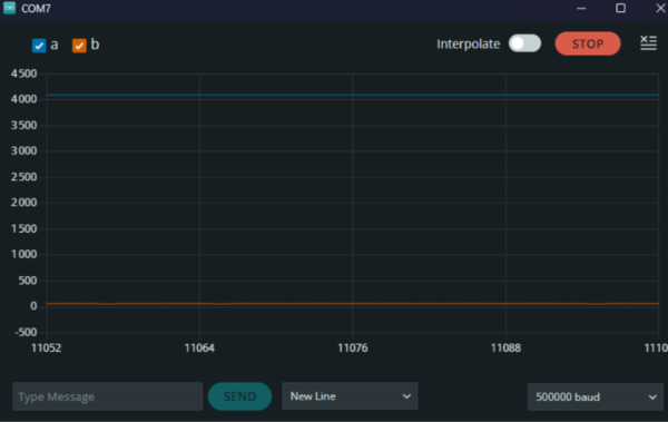 Blue signal: A0, Orange signal: A1
To go further, you can try connecting connecting other components to these pins, like a potentiometer as shown in the [introduction to embedded programming.]({{< relref "tutorials/electronics/introduction_to_embedded_prog/">}})
## Interpreting ADC values using sensitivity
If you want to convert ADC readings into human-readable voltages instead of LSBs [(Least Significant Bit)](https://en.wikipedia.org/wiki/Analog-to-digital_converter#:~:text=The%20change%20in%20voltage%20required%20to%20guarantee%20a%20change%20in%20the%20output%20code%20level%20is%20called%20the%20least%20significant%20bit%20(LSB)%20voltage.%20The%20resolution%20Q%20of%20the%20ADC%20is%20equal%20to%20the%20LSB%20voltage.), you'll need the ADC sensitivity. Use the formula:
$$
\text{sensitivity} = \frac{\text{range}}{(2^{\text{resolution}}-1)}
$$
Where:
* range: Voltage range (e.g., 0 to 5V)
* resolution: Bit resolution of your ADC
In my case, my voltage values range from 0 to 5V for a 12-bit ADC. So range = 5V, resolution = 12 bits, that gives us:
$$
\text{sensitivity} = \frac{\text{5}}{(2^{12}-1)} = 0,0012210012 \space V.LSB^{-1}
$$
Then you can multiply this sensitivity by your ADC value to get a voltage reading:
* For 0 LSB: \(0\times sensitivity = 0 \space V\)
* For 4095 LSB: \(4095\times sensitivity = 5 \space V\)
* For 1024 LSB: \(1024\times sensitivity = 1,25 \space V\)
---
## Credits
* **Writer:** [Ousmane THIONGANE](https://mowibox.github.io/)
* **Reviewer:**