# Introduction to embedded programmingDiscover the basics of embedded programming with Arduino through simple, progressive wirings: LEDs, buttons, potentiometers, and buzzers.
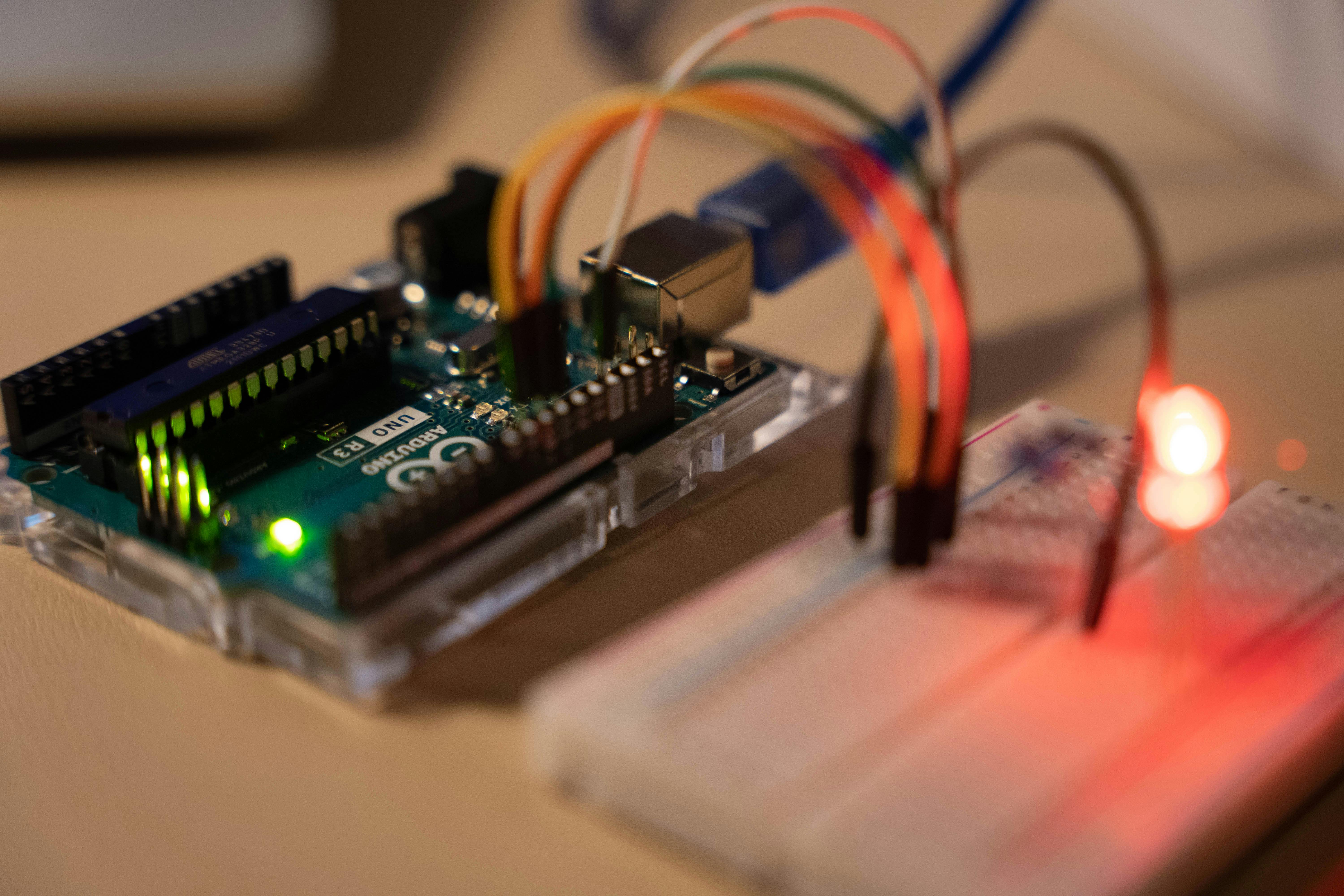
Embedded programming involves programming microcontrollers, which are small integrated circuits that bring together the essential elements of a computer. Microcontrollers can be found in a variety of everyday objects (robots, computers, cars...).
In this introductory course, you'll learn how to use an Arduino board and its associated software, in order to assimilate the basics of embedded programming for your future personal projects.
_For any comments or questions, feel free to email me at [ousmane.thiongane@outlook.com](mailto:ousmane.thiongane@outlook.com)._
## Requirements
### Software
* A computer with [Arduino IDE](https://www.arduino.cc/en/software/) software.
### Hardware
#### The microcontroller
* [An Arduino microcontroller board (e.g. an Arduino UNO)](https://store.arduino.cc/products/arduino-uno-rev3)
* [A USB type A-B cable](https://www.amazon.fr/PremiumCord-Connexion-Scanner-Blindage-Longueur/dp/B07HXSRMGJ/ref=sr_1_7?__mk_fr_FR=%C3%85M%C3%85%C5%BD%C3%95%C3%91&s=computers&sr=1-7)
#### Components
Components are fairly easy to find on online sales sites. One piece of advice I can give is to buy [component kits](https://www.amazon.fr/Elegoo-%C3%89lectronique-Breadboard-Potentiom%C3%A8tre-dapprentissage/dp/B01JD43262/ref=sr_1_12?__mk_fr_FR=%C3%85M%C3%85%C5%BD%C3%95%C3%91&sr=8-12) which already include the components listed below, with a few additional components that you can test on your own.
* [Three colored LEDs](/chroma/images/_led.jpg)
* [One push button](/chroma/images/_button.jpg)
* [Three resistors of 220 ohms](/chroma/images/_resistor.jpg)
* [One resistor of 10 kilo-ohms](/chroma/images/_resistor.jpg)
* [A potentiometer](/chroma/images/_pot.jpg)
* [An impedance buzzer](/chroma/images/_buzzer.jpg)
* [A breadboard](/chroma/images/_breadboard.jpg)
* [Some prototyping cables](/chroma/images/_cables.png)
## Missions
For each level, a circuit diagram will be proposed like the one below:
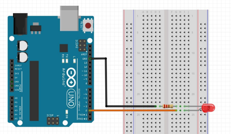
Try to build the circuit as shown. Once done, you can connect your Arduino board to your computer and open the Arduino IDE software. Let's explore the interface quickly with a code to turn on the red LED:
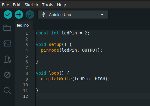
* The verify button :ballot_box_with_check: allows you to check your code for errors before sending it to the board.
* The upload button :arrow_right: sends the compiled code to the Arduino board for execution.
We define an integer corresponding to the board pin to which we've connected the LED, (here pin 2):
```ino
const int ledPin = 2;
```
As the LED is an output (i.e. we send current from the Arduino board to the LED to turn it on), we configure the `ledPin` pin as such with the `pinMode()` function:
```ino
pinMode(ledPin, OUTPUT);
```
In the `loop()` function, we use `digitalWrite()` to set the LED to the HIGH state, thus turning it on:
```ino
digitalWrite(ledPin, HIGH);
```
After compiling and uploading, all the code included in the `setup` function will run only once (in this case, the definition of `ledPin` as a digital output). As for the code in the `loop` function, it will loop indefinitely!
{{< callout context="caution" title="Tip" icon="outline/bulb" >}}
A few tips to get you started:
* A [cheat sheet](#cheat-sheet) containing syntax and useful functions is available further down the page.
* Don't forget the semicolon ";" at the end of each instruction.
* Use syntax highlighting and the verify button to check your code.
* Pay attention to lowercase/UPPERCASE (case sensitivity) in variable names: purple ≠ Purple.
* If you ever get stuck, a solution for each mission is also provided.
* Don't hit your computer (or anyone else) if it doesn't work!
{{< /callout >}}
### Level 1 - Blinking
#### Level 1 Wiring
{{< callout context="note" title="Mission" icon="outline/target-arrow" >}}
**Make the LED blink by changing its state every second.**
{{< /callout >}}
{{< details "Level 1 Solution - Blinking" >}}
_These codes are suggested corrections written by me. **Don’t treat them as the only solution** — there are many valid ways to solve the same problem._
_Find the one that suits you best!_
```ino {title = "level_1.ino", lineNos=true lineNoStart=1}
const int ledPin = 2;
void setup() {
pinMode(ledPin, OUTPUT);
}
void loop() {
digitalWrite(ledPin, HIGH);
delay(1000);
digitalWrite(ledPin, LOW);
delay(1000);
}
```
{{< /details >}}
---
### Level 2 - Traffic Light
#### Level 2 Wiring
{{< callout context="note" title="Mission" icon="outline/target-arrow" >}}
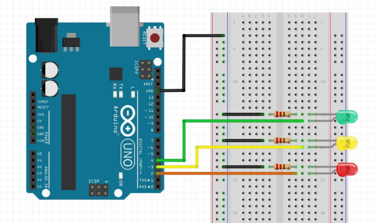
**Change the state of the 3 LEDs successively.**
{{< /callout >}}
{{< details "Level 2 Solution - Traffic Light" >}}
_These codes are suggested corrections written by me. **Don’t treat them as the only solution** — there are many valid ways to solve the same problem._
_Find the one that suits you best!_
```ino {title = "level_2.ino", lineNos=true lineNoStart=1}
const int redLed = 2;
const int yellowLed = 3;
const int greenLed = 4;
void setup() {
pinMode(redLed, OUTPUT);
pinMode(yellowLed, OUTPUT);
pinMode(greenLed, OUTPUT);
}
void loop() {
digitalWrite(redLed, HIGH);
digitalWrite(yellowLed, LOW);
digitalWrite(greenLed, LOW);
delay(1000);
digitalWrite(redLed, LOW);
digitalWrite(yellowLed, HIGH);
digitalWrite(greenLed, LOW);
delay(1000);
digitalWrite(redLed, LOW);
digitalWrite(yellowLed, LOW);
digitalWrite(greenLed, HIGH);
delay(1000);
}
```
{{< /details >}}
---
### Level 3 - Day, Night, Day...
#### Level 3 Wiring
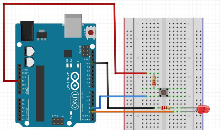
{{< callout context="note" title="Mission" icon="outline/target-arrow" >}}
**Command the LED to light up using a button.**
{{< /callout >}}
{{< callout context="caution" title="Tip" icon="outline/bulb" >}}
* Should the button be configured as an input or an output?
* Maybe there's a function to read the state of a digital pin... Maybe it's even in [cheat sheet](#cheat-sheet). Handy, isn't it?
{{< /callout >}}
{{< details "Level 3 Solution - Day, Night, Day..." >}}
_These codes are suggested corrections written by me. **Don’t treat them as the only solution** — there are many valid ways to solve the same problem._
_Find the one that suits you best!_
```ino {title = "level_3.ino", lineNos=true lineNoStart=1}
const int ledPin = 2;
const int buttonPin = 4;
void setup() {
pinMode(ledPin, OUTPUT);
pinMode(buttonPin, INPUT);
}
void loop() {
int buttonState = digitalRead(buttonPin);
if (buttonState == HIGH){
digitalWrite(ledPin, HIGH);
}
else{
digitalWrite(ledPin, LOW);
}
}
```
{{< /details >}}
---
### Level 4 - Day, Night, soft version
#### Level 4 Wiring
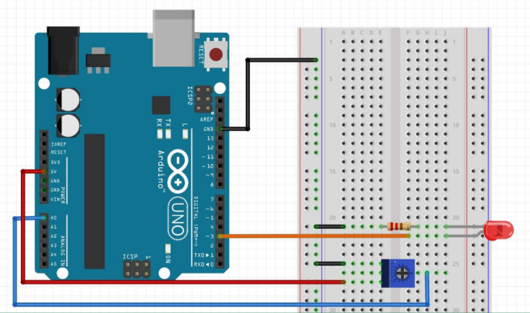
{{< callout context="note" title="Mission" icon="outline/target-arrow" >}}
**Control the LED brightness using a potentiometer.**
{{< /callout >}}
{{< callout context="caution" title="Tip" icon="outline/bulb" >}}
The potentiometer pin is connected to an analog port. Hmm... Analog... `analog`...
{{< /callout >}}
{{< details "Level 4 Solution - Day, Night, soft version" >}}
_These codes are suggested corrections written by me. **Don’t treat them as the only solution** — there are many valid ways to solve the same problem._
_Find the one that suits you best!_
```ino {title = "level_4.ino", lineNos=true lineNoStart=1}
const int ledPin = 3;
const int potPin = A0;
void setup() {
pinMode(ledPin, OUTPUT);
}
void loop() {
int potValue = analogRead(potPin);
int brightness = map(potValue, 0, 1023, 0, 255);
analogWrite(ledPin, brightness);
}
```
{{< /details >}}
---
### Level 5 - ♪ Happy Birthday ♪
#### Level 5 Wiring
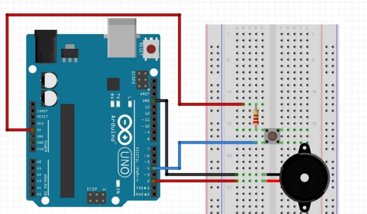 {{< callout context="note" title="Mission" icon="outline/target-arrow" >}}
**Play “Happy Birthday” when the button is pressed.**
{{< /callout >}}
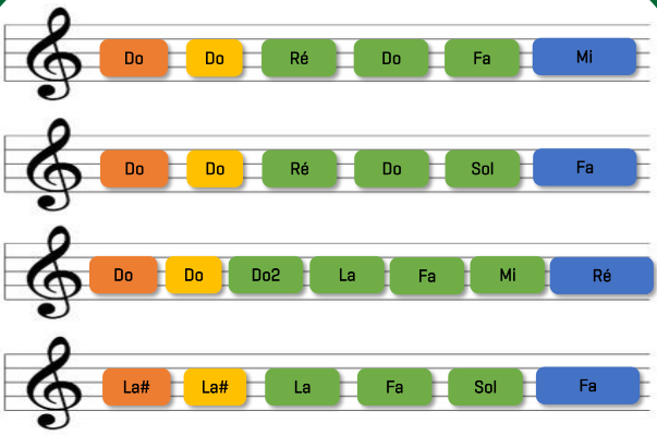
#### Frequencies of notes and (very) simplified "Happy Birthday" music sheet:
| Note | Do | Do# | Ré | Ré# | Mi | Fa | Fa# |
|--------|-----|-----|-----|-----|-----|-----|-----|
| f(Hz) | 262 | 277 | 294 | 311 | 330 | 349 | 370 |
| Note | Sol | Sol# | La | La# | Si | Do2 |
|--------|-----|------|-----|-----|-----|-----|
| f(Hz) | 391 | 415 | 440 | 466 | 493 | 523 |
{{< callout context="note" title="Mission" icon="outline/target-arrow" >}}
**Play “Happy Birthday” when the button is pressed.**
{{< /callout >}}
#### Frequencies of notes and (very) simplified "Happy Birthday" music sheet:
| Note | Do | Do# | Ré | Ré# | Mi | Fa | Fa# |
|--------|-----|-----|-----|-----|-----|-----|-----|
| f(Hz) | 262 | 277 | 294 | 311 | 330 | 349 | 370 |
| Note | Sol | Sol# | La | La# | Si | Do2 |
|--------|-----|------|-----|-----|-----|-----|
| f(Hz) | 391 | 415 | 440 | 466 | 493 | 523 |
{{< callout context="caution" title="Tip" icon="outline/bulb" >}}
There are 25 notes played in “Happy birthday”. We could use the brute-force method: writing 25 `tone()` & `noTone()` calls, but I'm sure there's a smarter way! In the simplified music sheet, one note color corresponds to a different duration — don't forget to vary delays accordingly.
{{< /callout >}}
{{< details "Level 5 Solution - ♪ Happy Birthday ♪" >}}
_These codes are suggested corrections written by me. **Don’t treat them as the only solution** — there are many valid ways to solve the same problem._
_Find the one that suits you best!_
```ino {title = "level_5.ino", lineNos=true lineNoStart=1}
#define DO 262
#define RE 294
#define MI 330
#define FA 349
#define SOL 392
#define LA 440
#define LAd 466
#define DO2 524
#define SIZE 25
const int buzzerPin = 2;
const int buttonPin = 4;
int frequences[SIZE] = {
DO, DO, RE, DO, FA, MI,
DO, DO, RE, DO, SOL, FA,
DO, DO, DO2, LA, FA, MI, RE,
LAd, LAd, LA, FA, SOL, FA
};
int durations[SIZE] = {
400, 200, 500, 500, 500, 900,
400, 200, 500, 500, 500, 900,
400, 200, 500, 500, 500, 500, 900,
400, 200, 500, 500, 500, 900
};
void setup() {
pinMode(buzzerPin, OUTPUT);
pinMode(buttonPin, INPUT);
}
void loop() {
int buttonState = digitalRead(buttonPin);
if (buttonState == HIGH){
happyBirthday();
}
}
void happyBirthday(){
for (int i = 0; i < SIZE; i++) {
tone(buzzerPin, frequences[i]);
delay(durations[i]);
noTone(buzzerPin);
}
}
```
{{< /details >}}
---
## Going further
Congrats if you've completed all the levels!
If it was too easy for you, try creating a project using all your components.
For example: a variable brightness traffic light that beeps when it turns red to warn pedestrians?
Feel free to search on the web for fun tutorials.
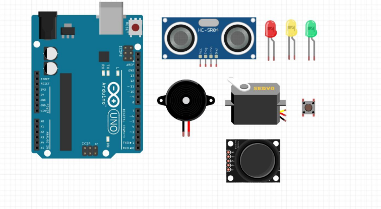
Arduino is a great platform to learn embedded programming quickly and build small projects.
But if you want to go further, you may look into **STM32 microcontrollers** — less beginner-friendly but widely used in industry and allows you to carry more complex projects.
---
## Cheat Sheet
### Variables
| Type | Description | Size |
|----------|---------------------------|-----------|
| `int` | Integer | 4 bytes |
| `float` | Decimal number | 4 bytes |
| `char` | Character | 1 byte |
| `double` | Double-precision decimal | 8 bytes |
### Operators
| Type | Operators |
|--------------|-------------------------------------------------|
| Arithmetic | `+`, `-`, `*`, `/`, `%` |
| Assignment | `=`, `+=`, `-=`, `%=`, `\|=`, `^=`, `<<=`, `>>=`|
| Logical | `&&`, `\|\|`, `<`, `>`, `<=`, `>=`, `==`, `!=` |
### Conditions
```ino
if (x < 3) {
printf("x is less than 3");
} else {
printf("x is 3 or more");
}
```
### Loops
```ino
int x = 0;
while(x < 5){
printf("I must not hit my computer.\n");
x++;
}
int sum = 0;
for(int i = 0; i < 100; i++){
sum += i;
}
```
### Preprocessor directives
```ino
// Inclusion of a library, in this case servo
#include
// Define constants
#define N 7
#define SIZE 3
#define SIZE2 6
```
### Arrays
```ino
int tab[SIZE] = {1, 8, 0, 5};
char tabchar[SIZE2] = {'c', 'h', 'r', 'o', 'm', 'a'};
// Initialize an array to 0
for (int i = 0; i < SIZE; i++) {
tab[i] = 0;
}
```
### Arduino Functions
| Function | Description |
|---------------------------------------|--------------------------------------------------------------------------|
| `pinMode(int pin, INPUT)` | Set the mode of a pin (`INPUT` or `OUTPUT`) |
| `digitalWrite(int pin, HIGH)` | Set a digital pin state (`HIGH` = 1, `LOW` = 0) |
| `digitalRead(int pin)` | Read the state of a digital pin |
| `delay(1000)` | Wait for 1000 ms (1 second) |
| `analogWrite(int pin, int dutyCycle)` | Create a PWM signal with `dutyCycle` ∈ [0; 255] |
| `analogRead(int pin)` | Read the value from an analog pin |
| `Serial.begin(int baud)` | Start serial communication (commonly `baud` = 9600) |
| `Serial.println("Chroma")` | Print “Chroma” to the serial monitor |
| `map(val, Imin, Imax, Omin, Omax)` | Rescale a value from range [`Imin`; `Imax`] to [`Omin`; `Omax`] |
| `tone(pin, frequency)` | Play a sound of frequency `frequency` on a buzzer |
| `noTone(pin)` | Stop the sound from the buzzer |
| `Servo myServo` | Create a servo control object |
| `myServo.attach(pin)` | Attach pin `pin` to the servo object |
| `myServo.write(90)` | Set the servo position (here to 90°) |
{{< callout context="tip" title="Did you know?" icon="outline/message-dots" >}}
The programming language used with Arduino is C++. It’s also used to build mobile apps, video games, desktop software, robotics, and more.
{{< /callout >}}
---
## Credits
* **Writer:** [Ousmane THIONGANE](https://mowibox.github.io/)
* **Reviewer:** Loubna LATRECHE