PWM signal generation tutorial
In this tutorial, you will learn how to generate a PWM signal using STM32 Cube IDE to control a servo motor.
Prerequisites
What is a PWM signal?
Pulse Width Modulation (PWM), is a technique used to control the power delivered to an electrical device.
In most digital systems, there are only two voltage levels: a high state (1) and a low state (0). There are no intermediate levels to vary the voltage (e.g., 0.5). To overcome this limitation, PWM works by varying the duration for which the signal is high while keeping the frequency constant.

Over a given period, the proportion of time the signal is high is called the duty cycle. By changing the duty cycle, we modify the average voltage applied to the component, allowing us to control a device with variable power.
This principle is used to control many devices, such as RGB LEDs, motor drivers, and so on.
In the context of controlling a servo motor, the PWM signal determines the angular position of the servo. By adjusting the pulse width, we can control the servo motor’s orientation.
Wiring and Configuration
For this tutorial, we will use a NUCLEO-L476RG board. The circuit diagram for a servo motor is shown below:
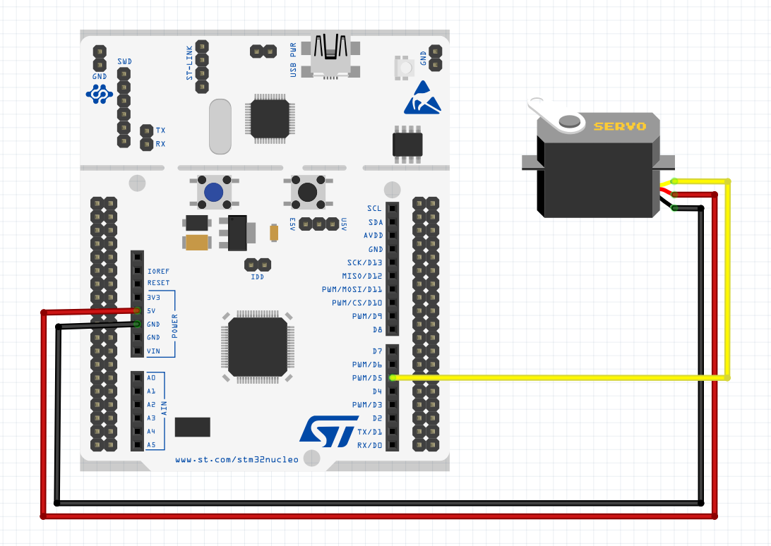
- Two wires connected to the servo’s +5V and GND (usually red for power and brown or black for ground).
- The third wire should be connected to a pin on the board capable of providing a PWM signal (most pins are labeled). In this example, we connect it to pin D5.
The next steps takes place on CubeIDE: create a new project and open CubeMX (to access the .ioc file).
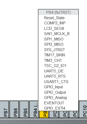
Identify which pin corresponds to D5. The mapping between “Dx” and “PAx” pins can be found online in the pinout documentation. For D5, it corresponds to PB4.
Configure the pin to use a timer and its available channel (in the form “TIMx_CHx”). For the NUCLEO L476RG, the only available configuration for D5 is TIM3_CH1.
In the left panel, set the following parameters:
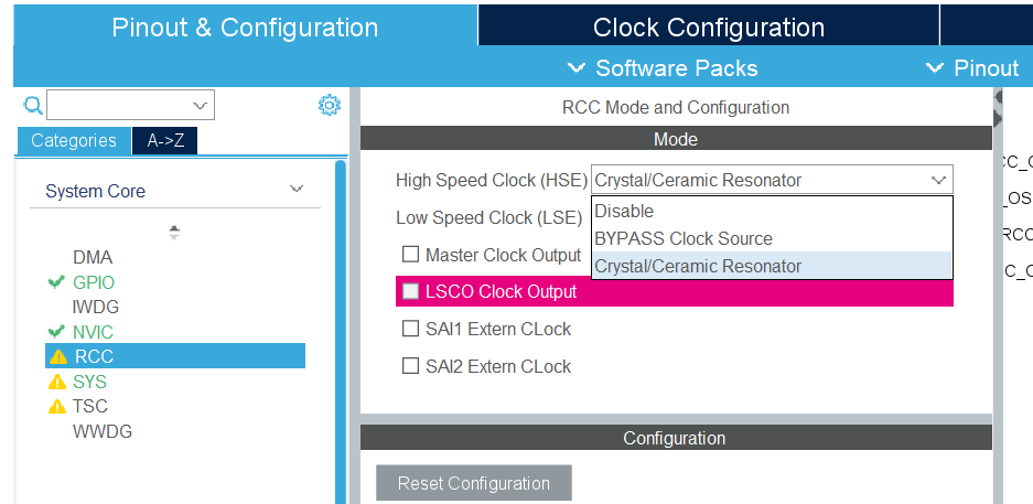
In the “System Core” section, select RCC.
- Set the High Speed Clock (HSE) to Crystal/Ceramic Resonator.
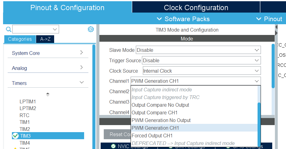
In the “Timers” section, select the timer you configured.
- Set the Clock Source to Internal Clock.
- Set the chosen channel to PWM Generation CHx (here, PWM Generation CH1).
Frequency Parameters
In the top Clock Configuration tab, you can see the frequencies at which the microcontroller timers operate. For the NUCLEO L476RG, it’s 80 MHz.
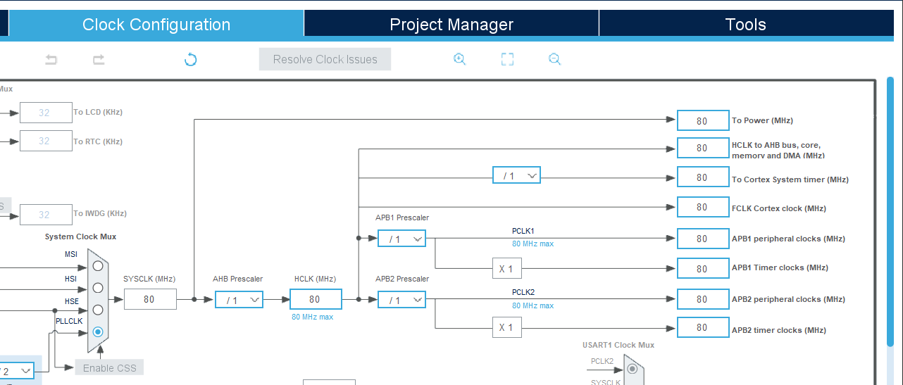
Howaver, according to the SG90 servo datasheet, the signal frequency should be around 50 Hz. The timer’s current frequency is far from 50 Hz, but fortunately, it is possible to divide the timer frequency to reach the desired value.
To do this, the following formula is used:

Where:
 is the timer frequency.
 is the frequency of the bus feeding the timer (here 80 MHz).
 (prescaler) is a register that divides the timer’s input frequency.
 (auto-reload register) defines the timer’s maximum count.
Knowing
, you just need to find a combination of PSC and ARR to get
 Hz. This can be done manually or using online calculators.
In this example, a suitable combination is
 and
and
 .
.
Did you know?
Several combinations can achieve 50 Hz. Note that the higher the value of
, the better the PWM resolution.
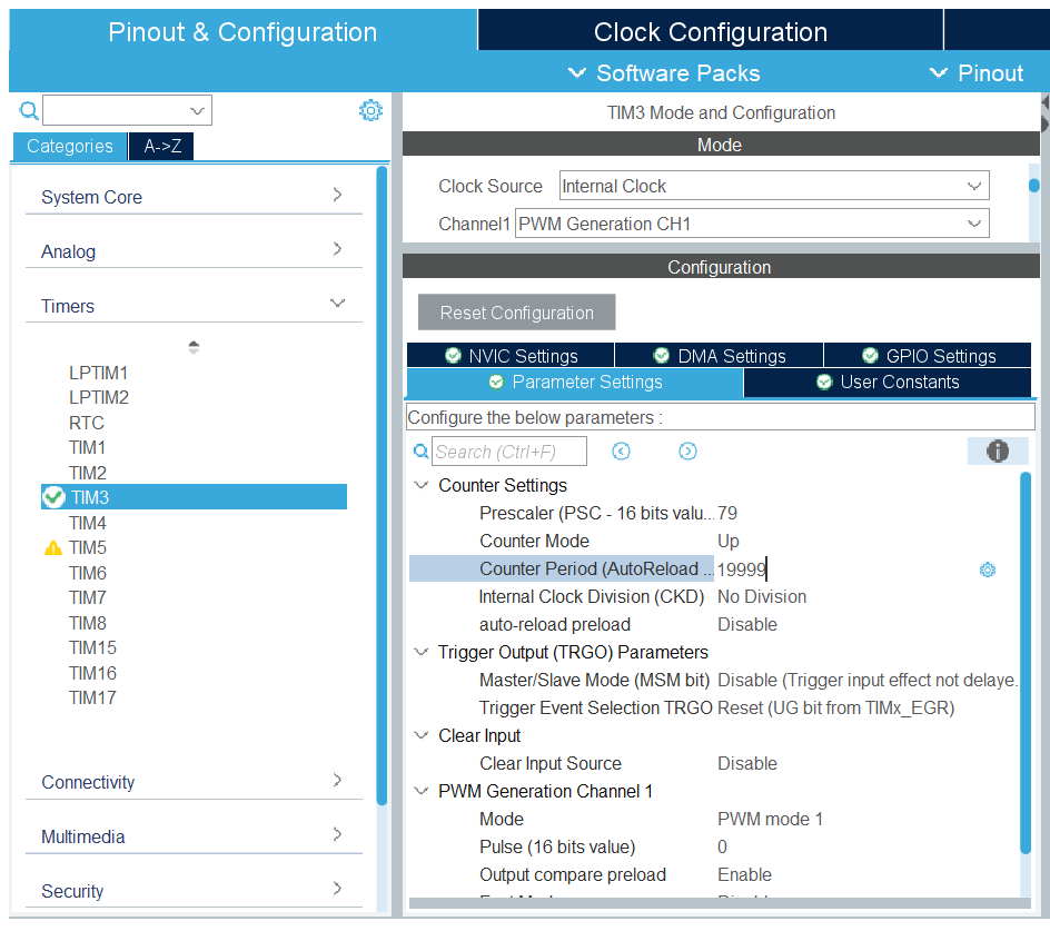
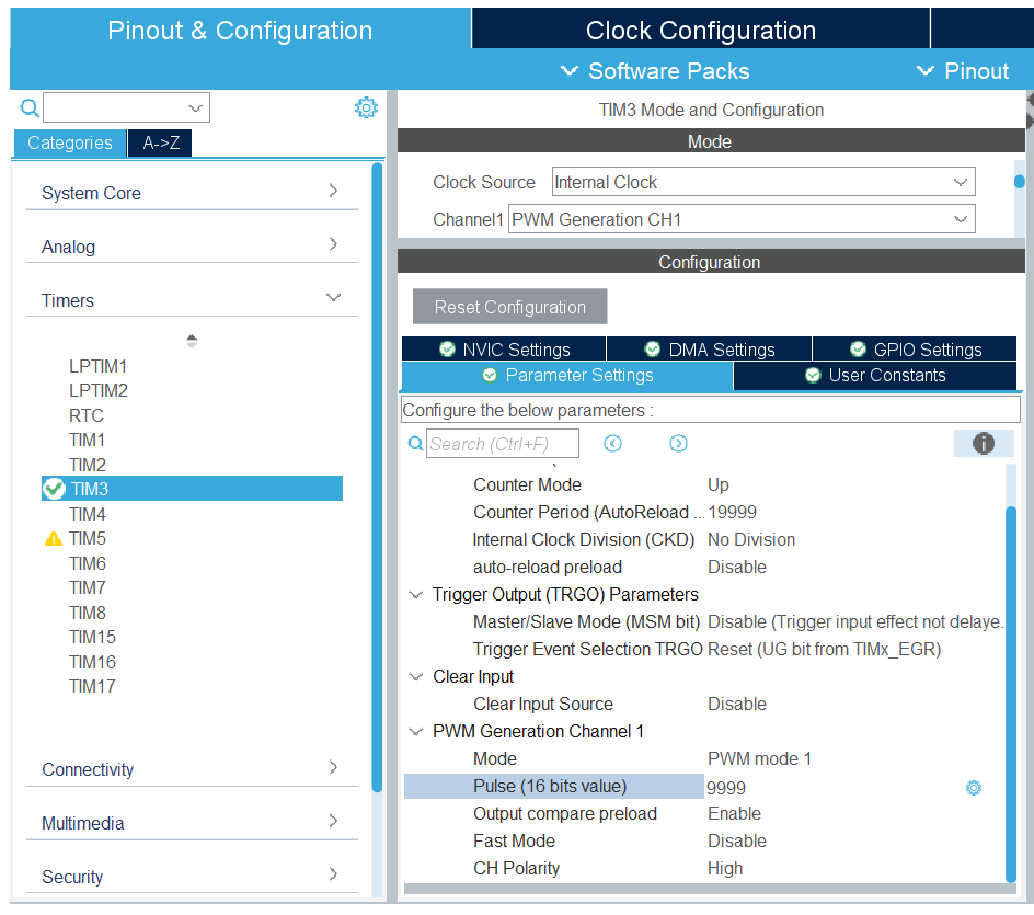
Once
and
are determined, enter these values in TIM3 under Parameter Settings:
Duty Cycle
The
 parameter is used to control the duty cycle of the PWM signal. In the same way as for dividing the frequency, there is a formula to calculate the value to enter in the
register based on the desired duty cycle
parameter is used to control the duty cycle of the PWM signal. In the same way as for dividing the frequency, there is a formula to calculate the value to enter in the
register based on the desired duty cycle
 :
:

For example, to set a 50% duty cycle with my values:

Enter this value in the timer parameters and generate the code:
Code integration
Before running the servo, you need to write a few lines in main.c. In the int main(void){} function, add:
 94MX_USART2_UART_Init();
 95MX_TIM3_Init();
 96/* USER CODE BEGIN 2 */
 97HAL_TIM_PWM_Start(&htim3, TIM_CHANNEL_1);
 98/* USER CODE END 2 */
 99
100/* Infinite loop */
HAL_TIM_PWM_Start(&htimX, TIM_CHANNEL_X); starts the PWM signal (replacing the “X” with the timer and channel values used).
Warning
Be sure to write your code between the tags “/* USER CODE BEGIN */” and “/* USER CODE END */”. Otherwise, your code will be deleted if you regenerate your files!
If you compile and upload the code to the board, you will notice that the servomotor… does not turn! This is because the servomotor is held in the position defined by the duty cycle, so you would need to vary this to get it to turn.
Bonus
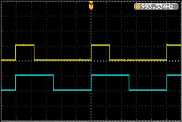
If you have an oscilloscope, you can still observe the PWM signal from your pin:
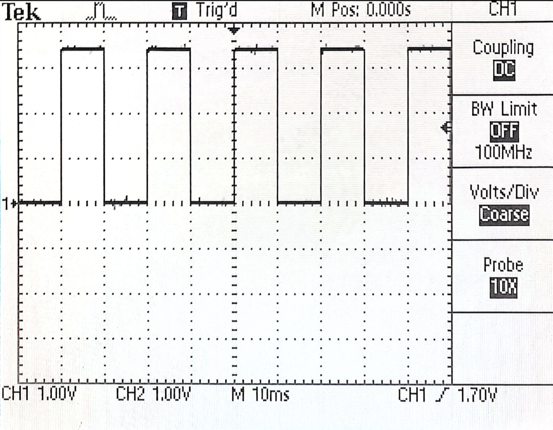
Thanks to the display tiles, we can clearly see that the signal period is 20 ms (i.e., 50 Hz). The duty cycle is
 .
.
Modifying the duty cycle
Rather than struggling to modify the
value manually by editing the .ioc file, it is possible to dynamically modify the pulse width directly in the code.
The macro __HAL_TIM_SetCompare(&htimX, TIM_CHANNEL_X, pulse) allows you to modify the duty cycle value of the channel associated with the selected timer. pulse is generally defined to represent the pulse width in microseconds.
The servomotor documentation states that:
Position “0°” (1.5 ms pulse) is middle, “90°” (~2ms pulse) is all the way to the right, “-90°” (~1ms pulse) is all the way to the left
With these values, it is possible to directly deduce the pulse values to be applied to the CCR register.
Here is a quick test to write in the while(1){} loop to change the angular position of the servomotor every second:
 97HAL_TIM_PWM_Start(&htim3, TIM_CHANNEL_1);
 98/* USER CODE END 2 */
 99
100/* Infinite loop */
101/* USER CODE BEGIN WHILE */
102while(1)
103{
104  // -90°
105  __HAL_TIM_SetCompare(&htim3, TIM_CHANNEL_1, 1000);
106  HAL_Delay(1000);
107
108  // 0°
109  __HAL_TIM_SetCompare(&htim3, TIM_CHANNEL_1, 1500);
110  HAL_Delay(1000);
111
112  // 90°
113  __HAL_TIM_SetCompare(&htim3, TIM_CHANNEL_1, 2000);
114  HAL_Delay(1000);
115  /* USER CODE END WHILE */
116
117  /* USER CODE BEGIN 3 */
118}
There you go!
Going further
Feel free to test different values to see how the servomotor behaves. Why not create a function that allows you to convert angle values directly into pulses? And of course, this signal generation process works with all compatible components. For example, you can easily adjust the brightness of an LED based on the pulse width you send it.
Credits
- Writer: Ousmane THIONGANE
- Latest update: December 2025
- Reviewer: